
CompuStar Install Manual: A Comprehensive Guide
This detailed manual, spanning 73 pages, covers CompuStar CM5200 series installation, including 12V & 24V ECU systems (Series B-2).
CompuStar systems represent a leading edge in vehicle security and remote start technology, utilized by over 100 million people globally across 185 countries. These systems offer convenience, peace of mind, and advanced control over your vehicle, accessible through long-range remote starters and cutting-edge smartphone integration.
The core of CompuStar’s functionality lies in its sophisticated control modules and telematics capabilities. The systems are designed for both professional installers and experienced DIY enthusiasts, with comprehensive guides available – like the 73-page manual for the CM5200 series – to ensure a seamless installation process.
Recent advancements, including the GPT-4o model, demonstrate a commitment to conversational AI integration, enhancing user experience and providing readily available support. CompuStar continually evolves, offering features like voice control and improved smartphone app synchronization.
Understanding CompuStar CM5200 Series
The CompuStar CM5200 series is a versatile platform, supporting both 12V and 24V ECU systems (Series B-2). This range allows compatibility with a broad spectrum of vehicles, making it a popular choice for installers and vehicle owners alike. The series is documented in a comprehensive installation manual, currently spanning 7 pages, offering detailed guidance for a successful setup.
Key features include advanced remote start functionality, security system integration, and telematics connectivity. The CM5200 series benefits from ongoing software updates and improvements, leveraging advancements in AI like ChatGPT for enhanced user support and troubleshooting.
Installation requires careful attention to wiring diagrams and adherence to safety precautions, as outlined in the complete installation and programming guide. Understanding the system’s capabilities is crucial for maximizing its potential.
Safety Precautions During Installation
Prior to commencing any CompuStar CM5200 series installation, a thorough review of the installation guide is paramount. Disconnect the vehicle’s battery to prevent accidental shorts and electrical damage. Exercise extreme caution when working with vehicle wiring, identifying circuits accurately before making any connections.
Always use appropriate tools and safety equipment, including insulated gloves and eye protection. Be mindful of potential hazards such as sharp edges and hot engine components. Improper installation can compromise vehicle safety systems, so meticulous attention to detail is essential.
Refer to the complete installation and programming guide for specific warnings and recommendations. Following these precautions ensures a safe and reliable installation, protecting both the vehicle and the installer.

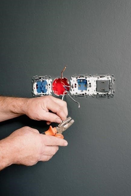
Vehicle Preparation & Wiring
Proper vehicle preparation involves locating and accurately identifying essential wiring diagrams, crucial for successful CompuStar CM5200 series integration and functionality.
Identifying Vehicle Wiring Diagrams
Accurate vehicle wiring diagrams are the cornerstone of a successful CompuStar installation. These diagrams detail the specific wiring configuration for your vehicle’s make, model, and year, pinpointing the location and function of critical wires. Sources for these diagrams include factory service manuals, online databases (often subscription-based), and dedicated automotive wiring resources.
Carefully verify the diagram’s accuracy against your vehicle’s actual wiring harness. Color codes can vary, and modifications may have been made previously. Pay close attention to connector pinouts and wire gauge. Understanding the vehicle’s security system wiring is also vital, as bypassing or integrating with it is often necessary for remote start functionality. Incorrect wiring can lead to system malfunction or vehicle damage, so proceed with caution and double-check all connections.
Locating the Ignition, Starter, and Accessory Wires
Identifying the ignition, starter, and accessory wires is crucial for proper CompuStar functionality. The ignition wire provides power when the key is in the “on” position, while the starter wire activates the vehicle’s starting motor. The accessory wire powers features like the radio and climate control when the key is in the “accessory” or “on” position.
These wires are typically found in the steering column harness. Use a multimeter to verify wire function; testing for 12V when the key is turned to the appropriate position. Consult your vehicle’s wiring diagram for precise wire colors and locations. Accurate identification prevents damage to the vehicle’s electrical system and ensures reliable remote start operation. Incorrect connections can lead to no-start conditions or unexpected system behavior.
Bypassing the Vehicle’s Security System
Modern vehicles often feature sophisticated security systems that can interfere with remote start operation. Bypassing these systems is frequently necessary for successful CompuStar installation. This typically involves utilizing a bypass module, which emulates the vehicle’s key fob signal to disarm the factory security system during remote start.
The specific bypass module required depends on the vehicle’s make and model. Proper programming of the bypass module is essential, often requiring access to a database of vehicle security protocols. Incorrect bypass configuration can result in a no-start condition or trigger the vehicle’s alarm. Always consult the CompuStar bypass module manual and vehicle-specific documentation for detailed instructions.
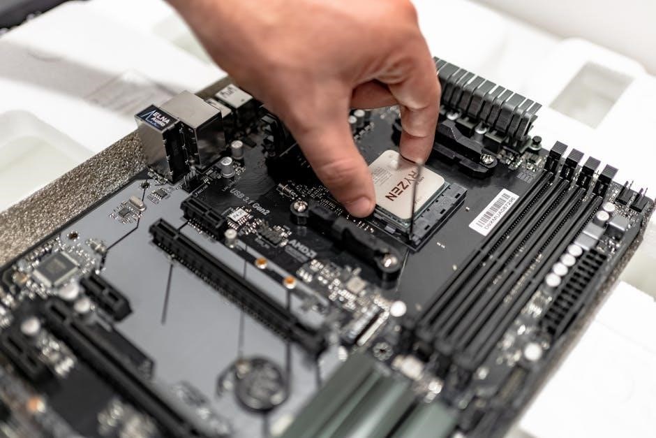
CompuStar Control Module Installation
Securely mount the control module and connect the main power and ground wires, then carefully wire the vehicle’s starter circuit for operation.
Mounting the Control Module
Selecting a suitable location is crucial for successful CompuStar installation. The control module should be mounted securely in a dry, concealed area within the vehicle, away from direct heat sources and moving parts. Avoid areas prone to water damage or excessive vibration.
Ensure the mounting location allows for easy access to the wiring harness for connections. Utilize the provided mounting brackets and screws to firmly attach the module. Double-check that the module is not obstructing any vehicle systems or components. Proper mounting prevents damage and ensures reliable operation of the remote start system. Consider the accessibility for future servicing or troubleshooting when choosing the final location.
Connecting the Main Power and Ground Wires
Establishing a solid power and ground connection is fundamental for CompuStar’s functionality. Connect the main power wire (typically red) to the vehicle’s positive battery terminal, utilizing a fused connection as close to the battery as possible. The fuse protects the system from overcurrent.
The ground wire (typically black) must be securely connected to a clean, unpainted metal surface of the vehicle’s chassis. Ensure a low-resistance connection for optimal performance. A poor ground can cause intermittent issues or system failure. Use appropriate ring terminals and securely fasten them. Verify the connections are tight and corrosion-free to guarantee a stable power supply for the entire system.
Wiring the Vehicle’s Starter Circuit
Accurate starter circuit wiring is crucial for reliable remote start operation. Identify the starter wire – typically a large gauge wire activating the starter motor. Connect the CompuStar’s starter wire (often a thick gauge wire, usually yellow) to this circuit.
Important: Do not directly connect to the starter solenoid terminal. Instead, tap into the control wire that activates the solenoid. A relay is often required to handle the starter circuit’s current draw. Proper relay installation prevents damage to the CompuStar control module. Double-check the wiring diagram for your specific vehicle to ensure correct identification and connection of the starter circuit.

Remote Start Functionality
Successfully wiring ignition and accessory circuits enables remote start. Programming the system and thoroughly testing operation are vital steps for a flawless experience.
Wiring the Ignition and Accessory Circuits
Precisely connecting the ignition and accessory circuits is fundamental for reliable remote start functionality; Identifying these wires within the vehicle’s wiring harness – often requiring a detailed wiring diagram – is the initial crucial step. The CompuStar system necessitates a secure connection to the ignition wire, enabling the system to simulate key-in-ignition activation.
Similarly, the accessory wire powers essential components like the radio and climate control during remote start. Correct polarity and secure connections are paramount to prevent electrical issues. Improper wiring can lead to system malfunction or even damage vehicle electronics. Careful attention to detail and adherence to the installation manual’s specific wiring schematics are essential for a successful installation and optimal performance of the remote start system.
Programming the Remote Start System
After completing the wiring, programming the CompuStar system is vital for proper operation. This process involves configuring the system to recognize the vehicle’s unique characteristics and the user’s remote transmitters. Utilizing the CompuStar programming modes – detailed within the comprehensive 73-page manual – allows technicians to customize settings like run-time duration and safety features.
Successful programming ensures the system responds correctly to remote commands, initiating the remote start sequence as intended. It’s crucial to follow the manual’s instructions precisely, as incorrect programming can lead to malfunctions. The system may require specific sequences of key turns and button presses to establish communication and finalize the configuration, guaranteeing a seamless user experience.
Testing the Remote Start Operation
Rigorous testing is paramount after programming to confirm the CompuStar remote start functions flawlessly. Begin by verifying the system responds to the remote commands – start, stop, and lock/unlock – from a reasonable distance, as specified in the 73-page installation guide. Observe the vehicle’s response, ensuring the engine starts smoothly and operates without any unusual noises or warning lights.
Check all safety interlocks, like the parking brake and gear selector, to guarantee the system prevents unintended starts. Cycle through various test scenarios, including multiple start/stop sequences, to validate reliability. Document any discrepancies or errors encountered during testing, referencing the troubleshooting section of the manual for potential solutions. A thorough test ensures customer satisfaction and system longevity.

Advanced Features & Connections
Explore connections for door locks, trunk release, and factory alarm integration, enhancing the CompuStar system’s functionality beyond basic remote start capabilities.
Connecting the Door Lock/Unlock Wires
Successfully integrating door lock and unlock functionality requires careful wiring, ensuring seamless control alongside the remote start system. Identify the vehicle’s door lock relay or direct control wires using a wiring diagram. Connect the CompuStar’s designated lock wire to the vehicle’s lock circuit and the unlock wire to the unlock circuit.
Proper polarity is crucial; incorrect wiring can lead to reversed operation or system malfunction. Test the connections thoroughly after installation, verifying both lock and unlock functions respond correctly to the remote commands. Some vehicles may require additional relays or interface modules for compatibility, especially those with advanced security or multiplexed wiring systems. Refer to the vehicle-specific application guide for detailed instructions and wiring schematics.
Wiring the Trunk Release Function
Enabling trunk release via the CompuStar system adds convenient remote access. Locate the vehicle’s trunk release solenoid wire, typically found near the trunk latch or within the vehicle’s wiring harness. Connect the CompuStar’s trunk release wire to this solenoid wire. It’s vital to confirm the correct wire, as incorrect connections could damage the vehicle’s electrical system.
Often, a relay is necessary to handle the current draw of the trunk release solenoid. Ensure the relay is properly wired and fused for safety; After installation, thoroughly test the trunk release function using the remote, verifying it operates smoothly and reliably. Consult the vehicle-specific application guide for precise wiring locations and any necessary relay configurations.
Integrating with Factory Alarm Systems
Seamlessly integrating CompuStar with a vehicle’s factory alarm enhances security and functionality. This often involves connecting CompuStar’s alarm disarm wire to the factory alarm’s disarm input. Careful consideration is needed to avoid triggering false alarms or disabling factory features. Consult the vehicle-specific application guide for precise wiring details and compatibility information.
Proper integration ensures the factory alarm disarms automatically upon remote start, preventing unwanted activation. Utilizing data interfaces, where available, provides more sophisticated control and avoids hardwire connections. Thorough testing is crucial to confirm the CompuStar and factory alarm work harmoniously, offering a comprehensive security solution.

Telematics & Smartphone Control
The CompuStar telematics system enables smartphone control and features, requiring communicator installation and app pairing for remote access and vehicle monitoring.
Installing the Telematics Communicator System
Integrating the CompuStar telematics system unlocks a suite of remote features, controlled via a smartphone application. The installation process requires careful attention to wiring and placement for optimal signal reception. Begin by locating a suitable mounting position for the telematics module, typically within the vehicle’s cabin, ensuring it has access to both power and a reliable cellular connection.
Connect the module to the vehicle’s power source, observing correct polarity, and ground it securely to the chassis. Proper grounding is crucial for stable operation. Following the wiring diagram, connect the necessary data lines to the CompuStar control module. Ensure all connections are firm and insulated to prevent shorts. Once physically installed, the system requires activation and pairing with the user’s smartphone through the CompuStar app, enabling remote start, door lock/unlock, and vehicle tracking capabilities.
Pairing the Smartphone App
After installing the Telematics Communicator System, seamless smartphone integration is essential. Download the official CompuStar app, available for both Android and iOS devices, offering a free and synchronized experience across all your devices; Launch the app and create a new account, or log in if you already have one. The app will guide you through the pairing process, typically involving entering the vehicle’s VIN or the telematics module’s unique ID.
Ensure your smartphone has Bluetooth enabled and is within range of the installed module. Follow the on-screen prompts to complete the pairing process, granting the app necessary permissions. Once paired, you’ll gain access to remote vehicle control, status updates, and customizable alerts, enhancing your overall CompuStar experience. The app provides the latest advancements from OpenAI.
Understanding Telematics Features
The CompuStar Telematics Communicator System unlocks a suite of advanced features accessible through the paired smartphone app. Enjoy remote start and stop functionality, allowing you to pre-condition your vehicle from anywhere with cellular connectivity. Monitor vehicle status, including door lock/unlock, alarm triggers, and battery voltage, providing peace of mind.
Geo-fencing capabilities enable you to define virtual boundaries and receive alerts when your vehicle enters or exits designated areas. Utilize the app for vehicle location tracking, helpful in various scenarios. Benefit from over-the-air updates, ensuring your system remains current with the latest features and improvements. More than 100 million users benefit weekly from these features.

Troubleshooting Common Issues
Addressing no-start conditions, remote start failures, and security system interference are crucial; Solutions involve verifying wiring, reprogramming, and resolving signal conflicts.
No Start Condition Troubleshooting
When encountering a no-start condition after CompuStar installation, a systematic approach is essential. First, verify the main power and ground connections to the control module, ensuring they are secure and receiving adequate voltage. Check the starter wire connection – confirm it’s properly connected to the vehicle’s starter relay control wire.
Next, investigate potential security system interference. The CompuStar system may require a bypass module to disable the factory alarm during remote start. Ensure the bypass module is correctly programmed for the specific vehicle. A faulty bypass module can prevent the engine from starting. Finally, double-check all wiring connections for accuracy and tightness, as a loose connection can interrupt the starting circuit. Utilize a multimeter to test voltage and continuity where necessary.
Remote Start Not Responding
If the CompuStar remote start isn’t responding, begin by checking the remote transmitter’s battery. A weak battery is a common cause of communication failure. Next, verify the control module is receiving power and ground. Confirm the antenna wire connected to the control module is securely attached and not damaged, as this impacts signal reception.
Programming errors can also cause this issue; re-verify the system programming, ensuring the correct vehicle parameters are entered. Interference from other electronic devices can sometimes disrupt the signal. Finally, check for any active security system faults that might be preventing the remote start from engaging. A diagnostic scan tool can help identify any error codes stored within the CompuStar system.
Security System Interference Solutions
When encountering security system interference with your CompuStar system, the first step is to meticulously re-check all wiring connections related to the vehicle’s factory alarm and immobilizer. Ensure proper isolation of the CompuStar module from any direct interaction with sensitive factory security circuits.
Sometimes, a bypass module is required to correctly interface with the vehicle’s security. Verify the bypass module is correctly programmed for the specific vehicle. If the issue persists, try relocating the CompuStar control module to a different position within the vehicle, away from potential sources of electromagnetic interference. A diagnostic scan can reveal error codes, guiding troubleshooting. Consider a firmware update for the CompuStar module, as updates often address compatibility issues.
Programming & Configuration
Explore programming modes, adjust guide rates for RA & Dec, and customize system settings to optimize performance and tailor the CompuStar experience to your needs.
Understanding Programming Modes
CompuStar systems utilize various programming modes to facilitate customization and optimal functionality. These modes allow installers and end-users to tailor the system’s behavior to specific vehicle characteristics and personal preferences. Accessing these modes typically involves specific key fob sequences or utilizing a programming interface.
Understanding the nuances of each mode is crucial for successful installation and configuration. Different modes control parameters like remote start duration, sensor sensitivity, and security features. Careful attention to the manual’s instructions is paramount to avoid unintended consequences or system malfunctions. Proper programming ensures seamless integration and reliable operation of the CompuStar system, maximizing its benefits for vehicle owners.
Adjusting Guide Rates (RA & Dec)
Within the CompuStar system’s programming modes, adjusting the Guide Rates for Right Ascension (RA) and Declination (Dec) is a critical step for precise autoguiding functionality. These rates, expressed as percentages of sidereal speed, dictate how quickly the system corrects for tracking errors during long-exposure astrophotography;
Lower percentages result in slower, more deliberate corrections, ideal for minimizing overcorrection and maintaining smooth tracking. Conversely, higher percentages provide faster response, suitable for challenging conditions or aggressive guiding. Fine-tuning these rates requires careful observation and iterative adjustments to achieve optimal performance. The manual provides detailed guidance on determining appropriate settings based on the specific telescope and mount setup.
Customizing System Settings
CompuStar’s advanced programming capabilities allow for extensive customization of system settings to tailor performance to individual vehicle requirements and user preferences. Beyond basic remote start functionality, users can configure parameters such as run-time duration, temperature-based start/stop thresholds, and security features.
The system supports adjustments to door lock/unlock behavior, trunk release activation, and integration with factory alarm systems. Detailed programming guides outline each setting, providing clear instructions for modification. Careful consideration should be given to each customization to ensure optimal operation and prevent unintended consequences. Proper configuration maximizes the system’s potential and enhances the overall user experience.